Assembly instructions for snes/nes usb PCB revision A
This page is for the shop.raphnet.net
online shop customers who have received a revision A PCB.
The assembly instructions found here are for the
SNES/NES controller/gamepad to USB adapter project using the
revision A PCB. A newer revision
is available on the project page.
Required equipment:
You will need at least the following tools:
- Soldering iron with preferably very small tip
- Solder wire. Small.
- Flux. This really eases soldering. Doing this job
without flux is very hard (but not impossible).
I like to use a water solube flux pen, like this one:
- Tweezers. For manipulating the small surface mount
components.
Recommended equipment:
- Surface mount soldering experience. If not, you should
at least have ordinary soldering skills. (This page is not a soldering
tutorial)
- Magnifier
- Desoldering braid
Assembly, step by step:
 Solder the 1.5 Kohms resistor. This resistor is identified
with the 152 numbers. This resistor is bigger than the others to
workaround an error in the PCB.
Solder the 1.5 Kohms resistor. This resistor is identified
with the 152 numbers. This resistor is bigger than the others to
workaround an error in the PCB.
 Solder the first 68 ohm resistor. (identified with the '680' numbers).
 Solder the second 68 ohm resistor. (identified with the '680' numbers).
 Solder the 10uf capacitor. Observe the capacitor orientation.
 Solder the first crystal capacitor.
 Solder the second crystal capacitor.
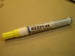
 Solder the 330 ohm resistor. (identified with the '331' numbers.)
 Solder the led. Observe how the green markings are oriented
while soldering.
Solder the led. Observe how the green markings are oriented
while soldering.
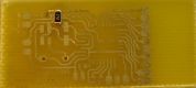
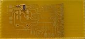
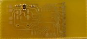
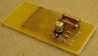
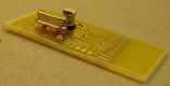
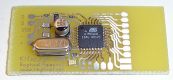
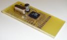
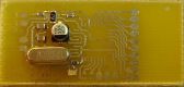 Solder the crystal. You can solder it on either side of the PCB. See
next 3 pictures for examples.
Solder the crystal. You can solder it on either side of the PCB. See
next 3 pictures for examples.

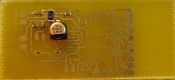
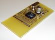
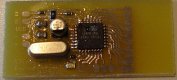 Solder the MCU. Tack it in place by soldering only one corner pin.
Align it correctly and solder the opposite pins. Finish by soldering all
remaining pins. Dont forget to use flux!
Solder the MCU. Tack it in place by soldering only one corner pin.
Align it correctly and solder the opposite pins. Finish by soldering all
remaining pins. Dont forget to use flux!
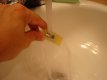 Dont leave the flux on the PCB. Rinse the board with water.
Supplemental pictures:


Page maintained by
Raphael Assenat

 Solder the 1.5 Kohms resistor. This resistor is identified
with the 152 numbers. This resistor is bigger than the others to
workaround an error in the PCB.
Solder the 1.5 Kohms resistor. This resistor is identified
with the 152 numbers. This resistor is bigger than the others to
workaround an error in the PCB. Solder the first 68 ohm resistor. (identified with the '680' numbers).
 Solder the second 68 ohm resistor. (identified with the '680' numbers).
 Solder the 10uf capacitor. Observe the capacitor orientation.
 Solder the first crystal capacitor.
 Solder the second crystal capacitor.
 Solder the 330 ohm resistor. (identified with the '331' numbers.)
 Solder the led. Observe how the green markings are oriented
while soldering.
Solder the led. Observe how the green markings are oriented
while soldering.
 Solder the crystal. You can solder it on either side of the PCB. See
next 3 pictures for examples.
Solder the crystal. You can solder it on either side of the PCB. See
next 3 pictures for examples.


 Solder the MCU. Tack it in place by soldering only one corner pin.
Align it correctly and solder the opposite pins. Finish by soldering all
remaining pins. Dont forget to use flux!
Solder the MCU. Tack it in place by soldering only one corner pin.
Align it correctly and solder the opposite pins. Finish by soldering all
remaining pins. Dont forget to use flux!
 Dont leave the flux on the PCB. Rinse the board with water.


